High-density 18650 NMC cells
.jpg?auto=format&fit=crop&w=400&q=80)
Large format LiFePO4 prismatic block

Terminal configuration detail
The Ultimate Builder Blueprint for Solar & Home Backup
Comprehensive Reference Guide & Complete Production Manual
Understanding the foundational chemistry of lithium-ion cells is the absolute first step in constructing safe and reliable energy storage systems. Lithium batteries operate by moving lithium ions between a cathode (positive terminal) and an anode (negative terminal) through an electrolyte solution. For DIY enthusiasts and solar integrators, two primary form factors dominate the market: the cylindrical 18650 cell and the prismatic LiFePO4 cell. The 18650, measuring 18mm in diameter and 65mm in length, typically utilizes NMC (Nickel Manganese Cobalt) chemistry. These cells are prized for their high energy density and are commonly used in portable power stations and electric vehicles. However, for stationary home backup, Lithium Iron Phosphate (LiFePO4) prismatic cells are the undisputed gold standard. LiFePO4 chemistry operates at a steady 3.2V nominal, tolerates significantly higher internal temperatures without degrading, and fundamentally resists thermal runaway. While a standard 18650 NMC cell might survive 300 to 500 deep discharge cycles before degrading to 80% capacity, a high-quality LiFePO4 cell can easily deliver 2,000 to over 6,000 cycles, offering a lifespan of 10+ years in daily solar applications. Selecting the correct form factor dictates not only the voltage and capacity of your final pack but also the safety profile and thermal management requirements of your entire power system architecture.
Constructing a reliable battery pack requires specialized assembly tools; attempting to use makeshift substitutes frequently ruins premium storage cells or creates severe short-circuit risks. The most critical tool in your arsenal is a precision spot welder. Traditional soldering irons introduce sustained, excessive heat directly into the battery cell's positive terminal. This heat can easily melt the internal plastic separators, permanently damaging the cell's pressure relief vents, and creating a latent fire hazard. A capacitive discharge (CD) or pulse spot welder delivers a massive but milliseconds-short burst of electrical current, cleanly fusing pure nickel strips to the cell terminals without transferring damaging heat into the cell's core. Furthermore, you must procure high-quality consumable raw materials. Always source pure nickel stripping; cheaper nickel-plated steel strips possess much higher electrical resistance, resulting in dangerous heat generation under sustained heavy loads. Other essential materials include rigid ABS plastic cell holders, which provide crucial air-gapped isolation and structural alignment, and barley paper (fish paper). This heavy-duty vulcanized fiber paper must be applied over positive cell caps before welding to prevent the nickel strips from vibrating and shorting against the outer negative cell casings during transport or operation.


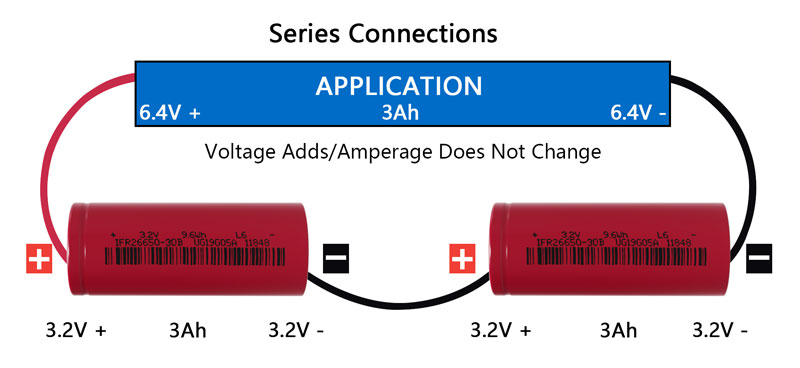
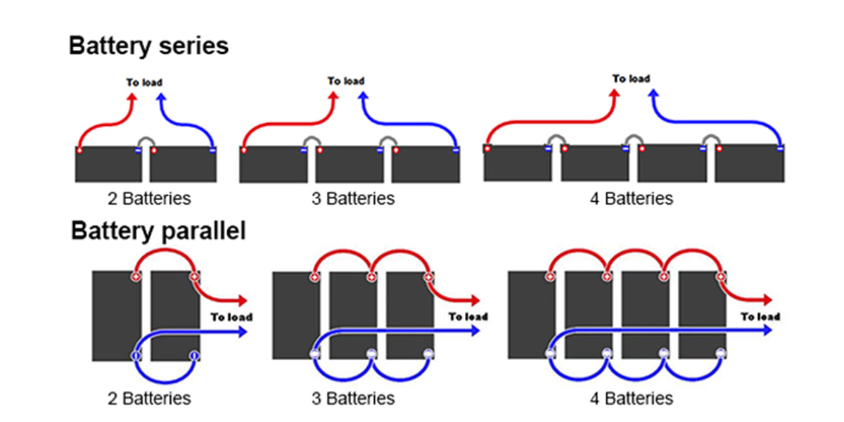
Combining individual battery cells into a uniform array allows builders to freely customize voltage and amp-hour ratings to meet precise engineering requirements. The total electrical capability of any assembly is determined by how connection paths are routed. In a Series (S) architecture, the negative terminal of one cell is linked to the positive terminal of the next. This configuration sums the operational voltage while keeping the overall storage capacity (Ah) equal to a single cell. For example, wiring four 3.2V LiFePO4 cells in series creates a 12.8V system, ideal for standard inverters. In a Parallel (P) architecture, all matching polarities are tied together (positive to positive, negative to negative). This sums the total capacity and maximum output current while leaving the system voltage unchanged. Linking four 100Ah cells in parallel creates a massive 400Ah battery bank at 3.2V. Most large-scale solar batteries use a combination of both, known as an "SP" configuration (e.g., 4S8P). When configuring parallel blocks, it is absolutely critical that all cells are at the exact same voltage (within 0.05V) before connection. Failing to match voltages will result in massive, unregulated current flows between cells as they violently attempt to equalize, permanently damaging internal chemistry and bypassing the BMS safety limits.

A Battery Management System (BMS) acts as the protective electronic brain of your energy storage pack. Raw lithium cells are highly volatile if overcharged, excessively discharged, or short-circuited. A dedicated BMS continuously monitors individual cell groups through a multi-wire balance harness. It enforces strict safety parameters, such as Over-Voltage Disconnect (stopping charge current if any cell exceeds 3.65V) and Under-Voltage Cutoff (disconnecting the load if any cell drops below 2.5V). Modern BMS units, particularly Smart BMS models equipped with Bluetooth, allow builders to monitor real-time voltages, temperatures, and current flow via smartphone applications. When wiring a BMS, the heavy-gauge main negative cable from your inverter connects directly to the BMS's B- port, while the battery pack's main positive cable bypasses the BMS entirely. The delicate balance wires (typically 4 to 16 small gauge wires) must be soldered sequentially from the lowest common ground (B0) up to the highest positive terminal (B4 for a 12V system). Reversing or crossing these balance wires during installation will instantly destroy the BMS microprocessor the moment power is applied, highlighting the need for meticulous multimeter verification.


Carefully following sequential physical steps during pack assembly is vital to prevent internal movement and short circuits under heavy, long-term use. The first step is cell matching; never mix cells of different ages, brands, or capacities. Use a multimeter to group cells with matched internal resistance profiles and equalized voltage levels. Next, load aligned cells into rigid interlocking plastic matrix spacers, alternating polarities (positive-up, negative-up) as required by your series wiring layout to minimize nickel strip length. Before any welding occurs, apply adhesive fish paper rings directly onto the positive cell caps. This thin insulation layer prevents the nickel stripping from vibrating against the outer negative cell casing. When spot welding, position the pure nickel strips across the aligned terminal groups and apply firm, consistent pressure with the welding probes. Finally, route the BMS balance wires, soldering them sequentially from the lowest ground up to the main positive terminal. Wrap the completed block in Kapton tape to secure the wiring harness and provide an additional layer of dielectric insulation against physical abrasion.



Lithium energy storage cells hold immense power potential; therefore, strict workshop safety procedures must be enforced during every step of the assembly process. Thermal runaway is a catastrophic chain reaction where an internal short circuit generates heat faster than it can dissipate. This heat boils the internal electrolyte, generating flammable hydrogen gas, eventually triggering self-sustaining chemical fires that cannot be easily extinguished with water. The primary defense against thermal runaway is physical construction and electrical insulation. Never place metal tools or loose wire snippets across exposed battery terminals; always remove personal jewelry, watches, and rings before handling open cells. Keep Class-D metal fire extinguishers and a bucket of dry sand nearby. Once the pack is electrically complete, wrap the entire assembly in flame-resistant Kapton polyimide sheeting. Finally, house the finished battery block inside a rigid, waterproof ABS plastic or aluminum enclosure. This enclosure prevents physical compression damage and provides a mechanical fire barrier between the high-energy cells and your living space.


Integrating a homebrew battery pack with solar equipment requires matching system voltage ranges and programming correct charging parameters into connected components. The battery bank interfaces directly with solar charge controllers and power inverters using heavy-gauge copper wiring, strictly protected by inline T-class fuses. Never connect an inverter directly to a BMS without a physical fuse; a sudden short circuit in the inverter can dump thousands of amps, melting wires and igniting fires. When programming your solar charge controller, set the Bulk/Absorption voltage to 14.4V for standard 12V LiFePO4 packs (3.6V per individual cell group). Unlike lead-acid batteries, lithium batteries do not require a continuous float charge; set the Float Voltage to 13.6V to reduce chemical stress once the cells are fully charged. Finally, program the Low Voltage Inverter Cutoff to shut down at 11.5V–12.0V. This ensures the inverter powers down safely before the underlying BMS is forced to trip its internal under-voltage protection, preventing sudden hard resets on your AC appliances and preserving the lifespan of the battery management system.


A newly constructed battery system requires rigorous diagnostic testing before being put into service, alongside proper ongoing maintenance to maximize operational lifespan. Never connect an untested battery pack directly to high power demands. First, perform static voltage balancing by leaving the newly assembled pack on a low-current balance charger. This ensures all parallel cell groups reach equal voltage baselines, allowing the BMS to function accurately. Next, conduct a controlled capacity test by discharging the pack through a calibrated electronic load meter to measure real amp-hour output against rated specifications. Use a thermal imaging camera or infrared thermometer to monitor nickel strips and connection joints under heavy load to identify high-resistance hotspots. Sourcing high-quality, authentic raw materials can be challenging for beginners. In North America and Europe, suppliers like Battery Hookup and NKON provide grade-A cells with official factory test documentation. In emerging markets in Africa and South America, source materials through established regional solar distributors or filter direct international storefronts (AliExpress, Alibaba) strictly for verified grade-A manufacturers. Always request manufacturer QR code verification logs to confirm cell authenticity.